Repairing a cheap digital scale
My wife had a small, cheap digital scale she liked. Got it off Amazon or some such, I think. Worked fine for her, for a few months or so. Then one day she brings to me and says it’s having problems.
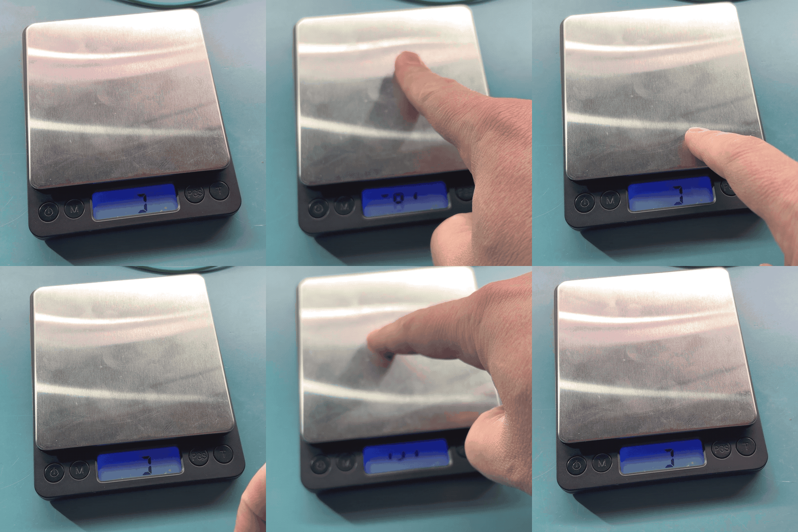
I turn it on, and press on it. Portions of the digits appear. I let off, and the portions of digits disappear. Repeat. Alright, it’s responding to weight on the scale. I figure the connection to the scale, and whatever custom IC is running the thing are fine. Something has happened to the display. Let’s take it apart and see what’s up.
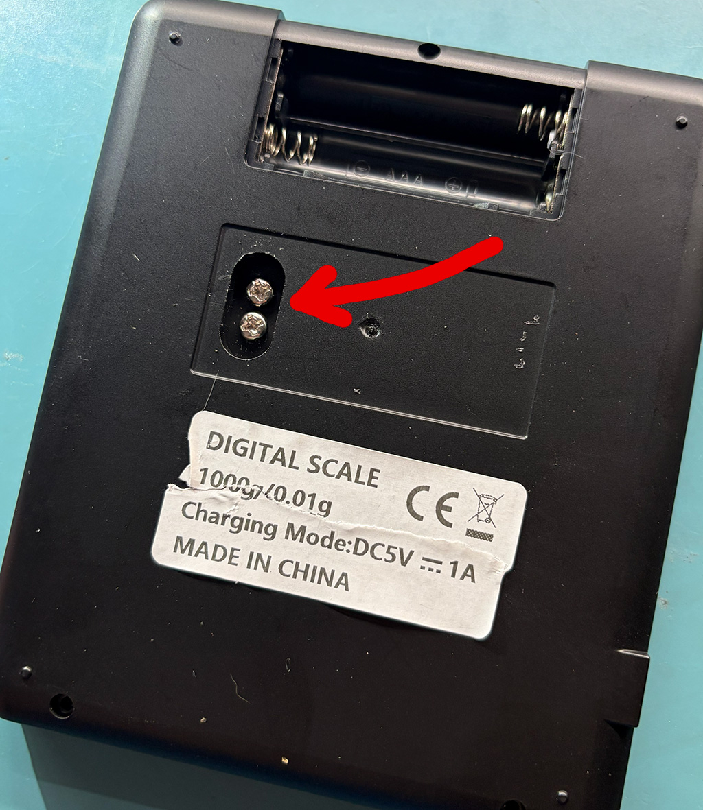
These screws are hidden under the label. They’re also the ones that hold the whole plate assembly to the case.
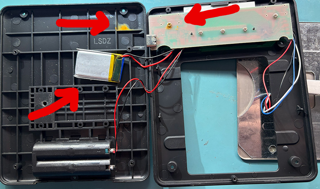
Looking at the top two arrows, there’s some sort of corrosion that must’ve come through the screw hole, and pooled down in the bottom of the case. That’s not encouraging.
We’ve also got a little LiPo pack, with no temperature sensing, and a distressing charging rate. When I first plugged it into a 5V supply through a power measurement widget, it reported 600mA of draw. That dropped to 550mA and then 500mA rather quickly, but unfortunately it sat there at half an amp for longer than I was comfortable with. I disconnected the power, and when I reassembled the whole thing I omitted the pack.
I would’ve expected a charging rate in the ballpark of 25mA to 150mA. 500mA is way too much, especially without any thermal sensor. I’m attributing all of that current to the charge rate, because a digital scale like this isn’t going to draw more than some tens of milliamps. If the charge circuit is linear, then the remainder of the input is the output to the battery. If the charge circuit is switching, then it’s even worse.
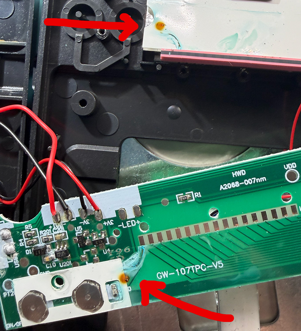
Here the PCB has been flipped over, towards the bottom of the image. At the top, the large white area is the back side of the LCD. The red and black foam strip on it is an “elastomeric connector”. When squished between the LCD and PCB, it connects the signals on one to the other. It actively requires a bit of compression to work.
We’ve also got some corrosion on the top here, that looks like it dribbled or migrated around on the PCB. I looked at all of the solder joints on the left side of the image, they were… fine. Electrically conductive. Most of them looked like they had a crust of flux on them. I scraped a lot of that off. Later when it was disconnected, I rinsed it off and scrubbed it with a brush. A pat with a paper towel, and by the time the soldering was done it seemed dry enough. Your mileage may vary.
We can see, even at this scale, that some of the pads connecting the epoxy-blobbed IC (off to the right, not visible) to the LCD are looking a little rough. Let’s zoom in…
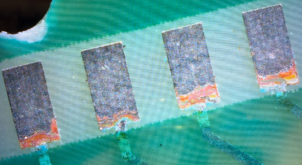
Yeah… those aren’t connected any more. There are 17 of them, I went down the line, scratching at the corroded whatever with my tweezers. It all came right off. Usually a bunch of the HASL next to it came off too, revealing corrosion underneath. I kept going until it stopped flaking off instantly. As I recall about two of the pads were okay, and the rest were reduced to 40% to 70% of their original area. All of the damage was on the same side, where the trace entered the pad.
I fluxed them all, put new solder on, removed it all with wick, fluxed it all and put solder on again and then flattened it with wick. I figured that’d help me clean up the area. Weirdly some patches of the “good” looking pre-existing HASL wouldn’t take solder. No idea what was going on there.
With all of the pads wetted, I went down past the 45 degree bend in all the traces that you see in the picture, and scuffed off the solder mask. It came off with surprising ease. Probably could’ve gotten it up with a harsh glare. I fluxed and tinned the exposed bit of trace. Finally I came back with 30 AWG kynar wire, stripped all the insulation off, tacked one end onto the trace, bent it to follow the existing PCB trace, and then soldered the other end to the pad. As you’ll see in the picture, I stripped the wire completely bare. It’d be nice to leave the insulation on in the middle, but then I would’ve needed to precisely measure the length of the wire before cutting and soldering. I wouldn’t have trusted the solder joints at either end to hold up to having insulation stripped from the other end.
Conveniently, the elastomeric connector didn’t mind the pads becoming 0.25mm taller. It naturally expects some compression, and apparently had at least that much room left in the “squishiness budget”. I wouldn’t want to use thicker wire, and briefly considered ordering some 34 AWG wire for the task.
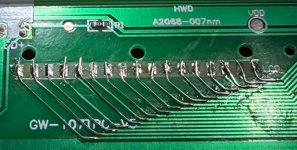
And there’s all the traces taken care of. Wasn’t too bad, just repetitive. In the end, the display worked again. The power button was a little hinky, I either got water inside of it, or perhaps disturbed the alignment. I think it’s the kind where it’s a bent bit of sheet metal held in place with adhesive. Regardless, it was usable again.
Conclusion!
I was told that no liquids had been spilled on it since my wife got it. As a chemist, she pays attention to that sort of thing, so I’m taking that as a given.
My best guess is that it was assembled using corrosive flux, and it wasn’t cleaned off. It sat there for awhile, until it was exposed to increased humidity, at which point it started to migrate into and along the elastomeric connector. Which I guess wasn’t affected? Or maybe in a few more months the scale will come back to me and I’ll find the connector has dissolved.